Part Names and Functions
This section explains the names and functions of parts that are related to the basic operations of the main unit.
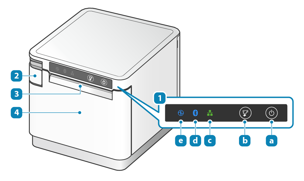
Front of main unit
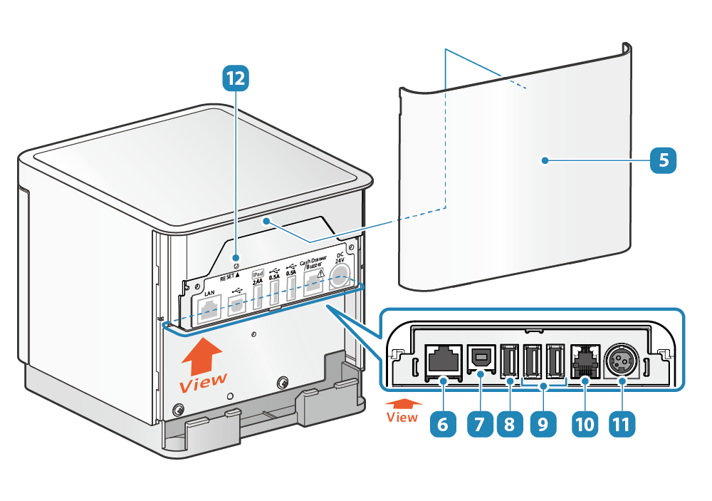
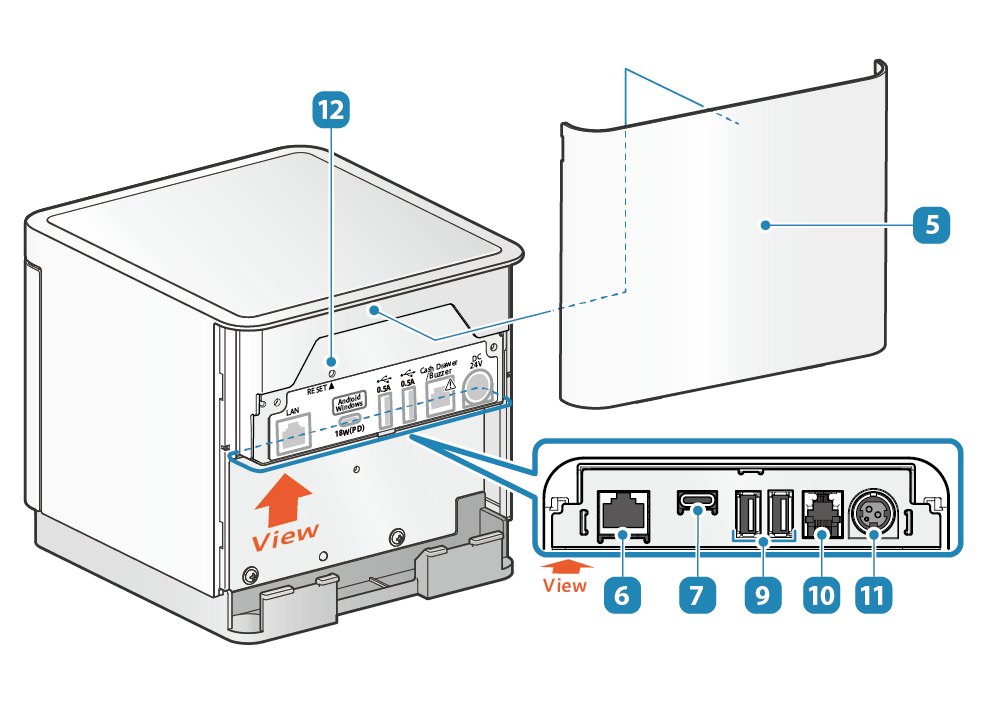
Back of main unit
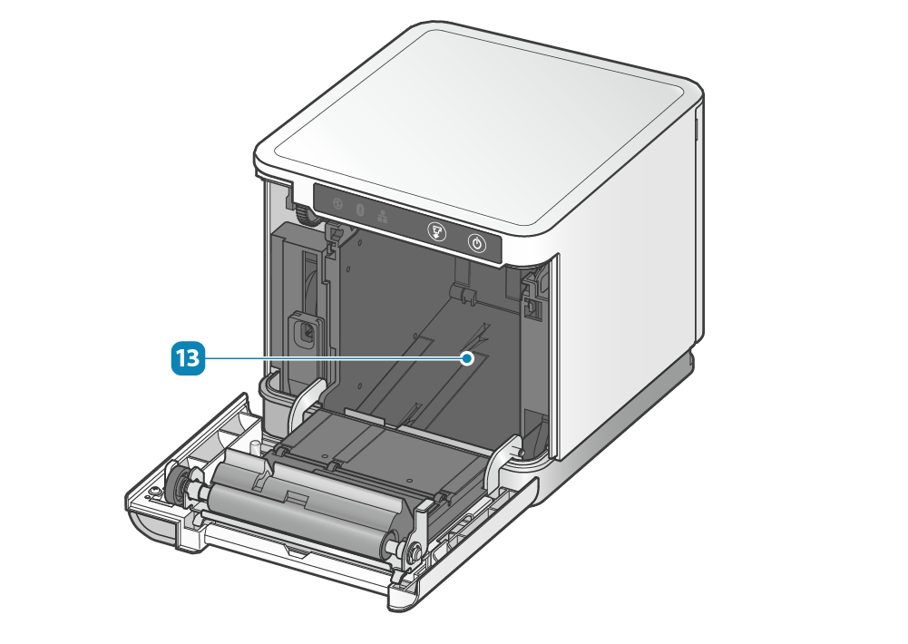
Inside of main unit
 Operation panel
- This panel provides printer operation switches and printer status indicator LED lamps.
 Power button
- Turns the power on/off.
Turn On/Off Power  FEED button
- Press this button to feed paper.
Also, use this button to perform Self-Printing.
Self-Printing  Network LED
- This LED lights up green according to the network connection status.
 Bluetooth LED <MCP31LB model only>
- Lights up blue according to the Bluetooth connection status.
Check Model  Power LED
- When the power is turned on, this LED lights up blue, red, and magenta according to the printer status.
LED Display  Opening lever
- Pull this lever to open the printer cover when setting the paper roll.
 Paper exit
- The printed paper is ejected from here.
 Printer cover
- Opens/Closes when setting the paper roll.
Paper Setup  Rear cover
- Remove this cover when connecting cables.
Remove/Mount Rear Cover  LAN connector
- Connect the LAN cable.
Connect LAN Cable  USB-B port
- Connect the Windows or Android device to the main unit to establish communication.
Connect USB Cable  USB-A (2.4A) port <MCP31LB, MCP31L, MCP31LBNH, MCP31LNH>
- Connect the iOS device to the main unit to perform communication and supply power (2.4A max.)
Also, connect USB-connectable products* or USB HID (Keyboard) class Devices* specified by Star Micronics to establish communication.
In addition, this port can supply power (1.5A max.) to tablets and other USB devices.
* There are restrictions if you use USB-connectable products or USB HID class (keyboard mode).
Connect USB Cable - iOS
For details, see Use USB Device.
Set Up External Devices - USB Port  USB-A (0.5A) port <MCP31LB, MCP31L>
- Connect USB-connectable products* or USB HID (Keyboard) class Devices* specified by Star Micronics to establish communication.
In addition, this port can also be used to supply power (0.5A max.) to USB peripherals.
* There are restrictions if you use USB-connectable products or USB HID class (keyboard mode).
Use Peripherals
For details, see Use USB Device.
Set Up External Devices - USB Port  External device drive connector
- This is a drive circuit to operate the cash drawer and external buzzer (options) and such.
Set Up External Devices - External device drive connector  Power Connector
- Connect the AC adapter that came with the main unit.
Connect AC Adapter  RESET switch
- Use this switch to initialize network or Bluetooth settings of the main unit.
Initialize Communication Settings - Information for ordinary users
- The device can be connected by USB to the mC-Print3 and used only if the application (or system) which is used supports the above USB devices. For the support status, check with the application (or system) provider.
- These devices cannot be used with general-purpose applications (such as Excel or Notepad).
- Information for developers
The operation of all commercially available USB HID class (keyboard mode) devices is not guaranteed.
Star Micronics does not check the operation of every kind of device. Therefore be sure to fully verify operation with the actual equipment before actually beginning use. Some commercially available devices are not able to communicate correctly with this product. - Rear cover
- Remove this cover when connecting cables.
Remove/Mount Rear Cover - LAN connector
- Connect the LAN cable.
Connect LAN Cable - USB-C port
- Connect the Android and Windows device to the main unit to perform communication and supply power (18W max.)
Connect USB Cable
Set Up External Devices - USB Port - USB-A (0.5A) port
- Connect USB-connectable products* or USB HID (Keyboard) class Devices* specified by Star Micronics to establish communication.
In addition, this port can also be used to supply power (0.5A max.) to USB peripherals.
* There are restrictions if you use USB-connectable products or USB HID class (keyboard mode).
Use Peripherals
For details, see Use USB Device.
Set Up External Devices - USB Port - External device drive connector
- This is a drive circuit to operate the cash drawer and external buzzer (options) and such.
Set Up External Devices - External device drive connector - Power Connector
- Connect the AC adapter that came with the main unit.
Connect AC Adapter - RESET switch
- Use this switch to initialize network or Bluetooth settings of the main unit.
Initialize Communication Settings - Information for ordinary users
- The device can be connected by USB to the mC-Print3 and used only if the application (or system) which is used supports the above USB devices. For the support status, check with the application (or system) provider.
- These devices cannot be used with general-purpose applications (such as Excel or Notepad).
- Information for developers
The operation of all commercially available USB HID class (keyboard mode) devices is not guaranteed.
Star Micronics does not check the operation of every kind of device. Therefore be sure to fully verify operation with the actual equipment before actually beginning use. Some commercially available devices are not able to communicate correctly with this product.  Paper roll holder
- Sets the paper roll.
Paper Setup
Use USB Device
Pay attention to the following points when connecting and using the USB-connectable products or USB HID class (keyboard mode) device with the mC-Print3.
Only one device of either our designated barcode reader or USB HID class (keyboard mode) can be connected.
Please direct any inquiries regarding support for USB HID class devices, please contact here .