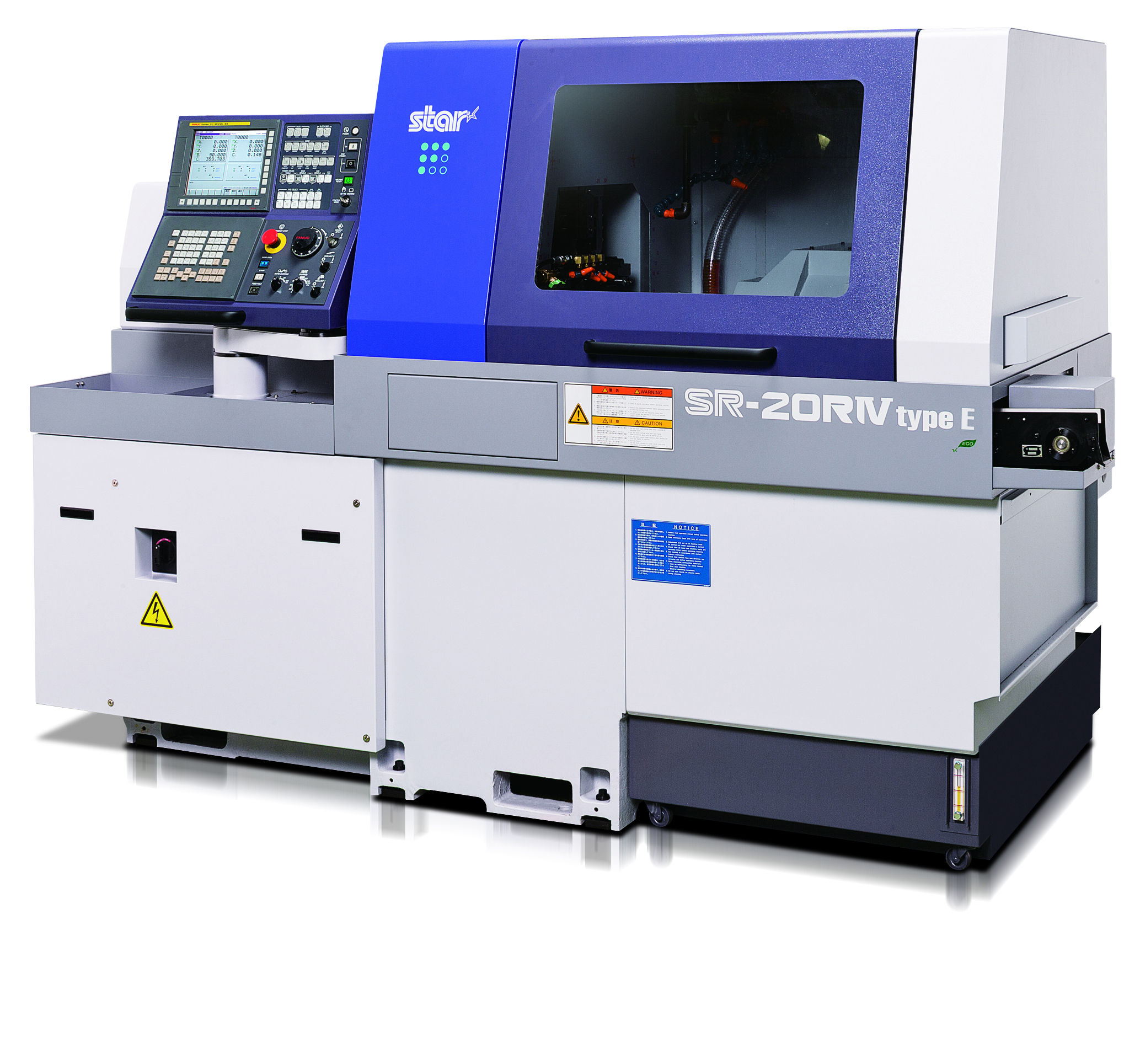
Release of SR-20RIV Type E, a Swiss-Type Automatic Lathe
– New product of our long-selling model, SR-20RIV, optimized for an even wider range of users –
Star Micronics Co., Ltd. (Head Office: Suruga-ku, Shizuoka-shi, Shizuoka; Representative Director, President, and CEO: Mamoru Sato) will launch the SR-20RIV Type E, a new product of its flagship SR-20RIV Swiss-type automatic lathe(*1), with maximum hole diameter of 20 mm, and begin sales in a wide range of industries, including automobiles and medical equipment.
Ever since the launch of the two types of SR-20RIV in 2012, Type A, which is equipped with a power driven tool unit for which the angle is manually adjustable, and Type B, which is equipped with a power driven tool unit with a tool swivel control axis (B-axis) capable of simultaneous 5-axis control, it has been highly regarded by customers in various industries, becoming a long-selling model with cumulative sales for the two types exceeding 2,400 machines.
Type E, which will be newly available for sale, employs a tool swivel control axis (B-axis) with simultaneous 4-axis control that was requested by many customers, making it capable of supporting a wider range of needs than conventional machines.
Start of Sales Scheduled for August 2025
Main Features
- [Power driven tool unit with B-axis control capable of simultaneous 4-axis control]
The angle of the power driven tool unit can be freely adjusted using an NC program. In addition, it can do machining of complex-shaped parts using simultaneous 4-axis control, such as 3D milling. - [High-rigidity tool post that employs a uniform load cross guide structure (*2)]
The gang-type tool post for front-end machining utilizes our proprietary uniform load cross guide structure. This reduces the moment load on the tool post guide rail during cutting, maintaining high tool post rigidity and realizing continuous operation for long periods of time with stable accuracy. - [Guide bush/non-guide bush(*3) changeover mechanism]
The mechanism makes it possible to change over at optimal specifications according to the full dimensions of the parts to be machined. In the case of long parts, the guide bush specification acts as a material run-out prevention device, enabling machining with high accuracy while suppressing deflection of the workpiece. In the case of short parts, the non-guide bush specification reduces the leftover material to be discarded, so material costs can be reduced. - [Wide variety of tooling variations]
Up to 41 tools can be mounted on the 27-position tool station. Flexible tooling allows a wide range of complex machining.
Main Specification
| Item | Specification | |
|---|---|---|
| Maximum hole diameter | 20 mm dia. | |
| Spindle unit maximum stroke | Guide bush specification | 205 mm |
| Non-guide bush specification | Material diameter x 2.5 (Max. 50 mm) | |
| Front side spindle | Maximum speed | 10,000min-1 |
| Motor output | 2.2 kW/3.7 kW | |
| Rear side spindle | Maximum speed | 10,000min-1 |
| Motor output | 2.2 kW/3.7 kW | |
| Power driven tool | Maximum speed | 8,000min-1 |
| Motor output | 2.2 kW | |
| Machine dimensions (W × D × H) | 2,334 mm × 1,200 mm × 1,695 mm | |
(*1) What is a Swiss-type automatic lathe?
The Swiss-type automatic lathe is a type of lathe that rotates materials such as metal, and presses a cutting instrument against the materials to cut them. It was invented in Switzerland in the 1870s as a machine for machining small precision parts such as watch parts. It is also called a “spindle-moving type automatic lathe”. It is characterized by its ability to cut long narrow parts with high precision due to the material grasped by the spindle unit being machined while fed at a certain distance from the guide bush, which acts as a material run-out prevention device.
(*2) What is a uniform load cross guide structure?
The gang-type tool post of the CNC automatic lathe is composed of X-axis and Y-axis slide tables. Each axis is usually supported by four linear guide bearings (eight in total). The uniform load cross guide structure indicates a tool post structure equipped with eight linear guide bearings evenly arranged around the guide bush, which is the cutting point where load is generated during machining. By distributing the load evenly to eight linear guide bearings, the load applied to each linear guide bearing is minimized and tool post rigidity is improved. The employment of this tool post structure enables extended continuous operation with stable accuracy and prolongs the service life of linear guide bearings.
(*3) What is the non-guide bush specification?
The non-guide bush specification is a Swiss-type automatic lathe with the guide bush that acts as a material run-out prevention device removed. It is unsuitable for machining of long narrow parts, however, in the case of short parts that do not deflect even without a guide bush, the length of leftover material that is discarded without being able to be machined due to the machine structure can be reduced by about one-third of that for the guide bush specification.
End