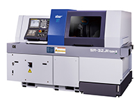
Swiss Type Automatic Lathe SR-32RII Released
Renewal of Best-Selling Model for Large-Diameter Machining by Adopting a Modular Design
Features of SR-32JII
High Rigidity and High Accuracy
- The gang-type tool post employs a rigid slanted slide guideway structure.
- The non-guide bush type uses a spindle sleeve slide guideway structure (NOTE 4) to support the cutting force on the slide guideway and ensure the headstock rigidity.
- Type B employs a slanted dovetail structure for Y2 axis sliding surface of the backworking tool post to ensure the tool post rigidity.
- Both the main and sub spindles employ a built-in motor to improve indexing accuracy through a built-in sensor.
High Functionality
- Acording to the workpiece overall length, the guide bush type and non-guide bush type can be switched over.
- Power tools on the gang-type tool post include two types – 5-axis type and 6-axis type.
- The backworking tool post of type A is equipped with a 6-axis unit. By combining with optional features, a power tool unit can be mounted on all positions.
- The backworking tool post of type B is equipped with an 8-axis unit with Y2-axis control function. A power tool unit can be mounted on all positions as a standard feature.
NOTE 1: Swiss-type automatic lathe
The Swiss-type automatic lathe was devised as watch component processing machinery in Switzerland in 1870s. Known as a “sliding head-type automatic lathe” as well, it has remarkable characteristics of high-precision cutting of components with longer length compared with the diameter.
In general, if long and narrow parts are processed with a general-purpose lathe, flexure will occur on the workpiece, making finishing with the correct dimensions impossible. The Swiss-type automatic lathe utilizes a guide bush to function as a material steady rest. The tool, positioned at a certain distance from the guide bush, gives a cutting motion only the direction of outside diameter. This allows the workpiece to be cut accurately with no flexure. As for axial motion, the headstock, rather than the tailstock, moves while clamping a workpiece.
NOTE 2: Slanted slide guideway structure
The machine main body base and the tool post are slanted and each sliding surface is in a trapezoidal shape, called a dovetail structure. This structure allows each sliding surface to come into contact with its entire plane to improve the machine rigidity. The ball screw center and the cutting point are close to each other to reduce a load (moment load) applied in the direction of torsion caused by cutting resistance.
NOTE 3: Non-guide bush type
This is a sliding head-type automatic lathe which is designed based on the Swiss-type automatic lathe with a guide bush dismounted. Without a guide bush, it is not well suited for machining narrow and long parts. If the workpiece is short and does not deflect, however, such material can be handled effectively.
With the Swiss-type automatic lathe, the rear side of a bar material needs to be handled as waste as a portion equivalent to the size of the guide bush structure which functions as a steady rest for the material cannot be machined.
The non-guide bush type reduces the waste to about 1/3 in length compared to the waste made by the guide bush type.
NOTE 4: Spindle sleeve slide guideway structure
This structure has a sliding surface machined according to the outer diameter of the head stock spindle sleeve, which moves while clamping the workpiece. By eliminating the gap between the spindle sleeve and the guideway, the structure supports the cutting load applied to the head stock through the slide guideway and improves the head stock rigidity.

 In addition, a flip-up door is incorporated to ensure sufficient work space inside the machine and a swing-type panel is used to enable the operator to operate the machine at the best position.