Start Micronics to Launch SB-16III, the CNC Swiss-Type Automatic Lathe
Expansion of SB series lineup with a reputation for high rigidity and accuracy
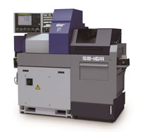
Star Micronics has developed SB-16III, a new model of “SB Series” Swiss-Type Automatic Lathe (Note 1), capable of machining workpieces of maximum 16-mm diameter, aiming to serve machining of workpieces for the automotive, information communication, and other devices mainly in the Japanese and Asian markets. The product is scheduled to launch in April 2020.
Equipped with the highly rigid tool post which has our company’s unique slant-type slide guideway structure (Note 2), the SB Series enables continuous machining with stable accuracy. Since 2003, when SB-16, the initial model of the series was released, the series has been our company’s best seller, earning a strong reputation in the market.
To meet a wide range of needs in the market, the SB16III was designed to reduce the footprint of the machine with selected functionalities of the current models: SB-12R/16R/20R.
Additionally, this model adopts the latest version of NC system, installed with a variety of help features including the alarm help function which enables checking of alarm contents on NC screen. Furthermore, the NC screen is mounted at an appropriate angle to the operator to ensure improved operability and workability.
Features of SB-16III
- It is equipped with the highly rigid tool post which has our company’s unique slant-type slide guideway structure which enables a long-time continuous machining with stable accuracy.
- The C-axis control function is installed as standard in the main and sub spindles.
- As an option, the product lineup newly includes the coolant-through type tool holder, which enables high-pressure supply of coolant through the inside of the tool from its tip without external pipes.
- A 10.4-inch color display is equipped with NC screen to improve visibility for operators.
- Various help functions which support operators’ daily work are installed to improve workability for setup and maintenance.
Main Specifications
| (1) Max. machining diameter | ⌀ 16 mm | ||
|---|---|---|---|
| (2) Max. headstock stroke | Stationary Guide Bush: | 205 mm | |
| Rotary Guide Bush: | 155 mm | ||
| (3) Max. main spindle speed | 10000 min-1 | ||
| (4) Main spindle motor | 2.2 kW (continuous) / 3.7 kW (15 min/60 %ED) | ||
| (5) Max. sub spindle speed | 9000 min-1 | ||
| (6) Sub spindle motor | 0.55 kW (continuous) / 1.1 kW (15 min/50 %ED) | ||
| (7) Gang-type tool post specifications | |||
| Tool(Selectable from the right) |
12 mm x 6 tools 12 mm x 5 tools 10 mm x 6 tools |
||
| Sleeve holder | 4 tools | ||
| Power tool(Selectable from the right) |
2-spindle cross drilling unit for ER11 2-spindle cross drilling unit for ER16 3-spindle cross drilling unit for ER11 3-spindle cross drilling unit for ER11/16 3-spindle cross drilling unit for ER16 |
||
| Max. spindle speed |
ER11: 7500 min-1 ER16: 5000 min-1 |
||
| Drive motor | 0.5 kW | ||
| (8) Back working tool post specifications | Stationary tool: 4 tools | ||
| (9) Front machining capability | |||
| Stationary tool | Max. drilling capability | ⌀ 10 mm | |
| Max. tapping capability | M8 x P1.25 | ||
| Power tool | Max. drilling capability | ER11: ⌀ 4 mm | |
| ER16: ⌀ 6 mm | |||
| Max. tapping capability | ER11: M3 x P0.5 | ||
| ER16: M5 x P0.8 | |||
| (10) Back machining capability | |||
| Stationary tool | Max. drilling capability | ⌀ 8 mm | |
| Max. tapping capability | M6 x P1.0 | ||
| (11) Machine dimensions (W x D x H) | 1861 x 1060 x 1750 mm | ||
NOTE 1: Swiss-type automatic lathe
The Swiss-type automatic lathe was devised as watch component processing machinery in Switzerland in 1870s. Known as a “sliding head-type automatic lathe” as well, it has remarkable characteristics of high-precision cutting of components with longer length compared with the diameter.
In general, if long and narrow parts are processed with a general-purpose lathe, flexure will occur on the workpiece, making finishing with the correct dimensions impossible. The Swiss-type automatic lathe utilizes a guide bush to function as a material steady rest. The tool, positioned at a certain distance from the guide bush, gives a cutting motion only the direction of outside diameter. This allows the workpiece to be cut accurately with no flexure. As for axial motion, the headstock, rather than the tailstock, moves while clamping a workpiece.
NOTE 2: Slanted slide guideway structure
The machine main body base and the tool post are slanted and each sliding surface is in a trapezoidal shape, called a dovetail structure. This structure allows each sliding surface to come into contact with its entire plane to improve the machine rigidity. The ball screw center and the cutting point are close to each other to reduce a load (moment load) applied in the direction of torsion caused by cutting resistance.