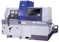
Swiss-Type Automatic Lathe SR-38 Newly Released
With a Balance-Cut Structure that Demonstrates Power in OD Cutting of
Large-Diameter Parts
Features of SR-38
High Functionality
- The portal type tool post for front-side machining is equipped with a rear tool holder incorporating an X-axis control function. Simultaneous rough machining and finish machining together with the front tool holder exerts great power in OD cutting of workpieces with large depth of cut.
- Type A has an angle adjustable power tool unit for slant machining of slant holes, etc. by adjusting angle as required.
- Type B has a power tool unit with a B axis control function for flexible slant machining by NC control.
- The eight-spindle back-working unit with a Y-axis control can accommodate a power tool at all positions.
High Rigidity and High Accuracy
- The portal-type tool post for front-side machining incorporates a “uniform load cross guide structure” which minimizes a moment load applied to the tool post guide rails during cutting and ensures high rigidity.
- Both the main and sub spindles use a built-in motor, and a built-in sensor improves spindle indexing accuracy.
- Axis control by the Star Motion Control System deadens vibration caused by extreme acceleration or deceleration during axis movement. (Type B)
High Productivity
- The balance-cut function, which enables both rough machining and finish machining simultaneously, contributes to the reduction of machining time.
- The eight-spindle unit with a Y-axis control function for rear-side machining is mounted for reduction of machining time by employing the efficient process split between the front and rear sides as well as simultaneous machining.
- The Star Motion Control System is employed to minimize non-cutting time. (Type B)
Major Specifications
| Max. machining diameter | ø 38mm | ||
|---|---|---|---|
| Max. headstock stroke | 320 mm | ||
| Max. main spindle speed | 7000 min-1 | ||
| Main spindle motor | 7.5kw (continuous) / 11kw (10min/25%ED) |
||
| Max. sub spindle speed | 7000 min-1 | ||
| Sub spindle motor | 3.7kw (continuous) / 5.5kw (10min/40%ED) |
||
| Gang-type tool post specifications | Tool | [Front side] | 5 |
| [Rear side] | 2 | ||
| Sleeve holder | Front working stationary tool | 5 | |
| Back working stationary tool | 5 | ||
| Power tool | For cross drilling only | 4 | |
| Cartridge type | 2 pos. | ||
| Angle adjustable power tool (type A) |
For front working | 3 | |
| For back working | 3 | ||
| Power tool with B axis control (type B) |
For front working | 3 | |
| For back working | 3 | ||
| Back 8-spindle unit | No. of tools | [Stationary tool] | Max.8 |
| [Power-driven tool] | Max.8 | ||
| Front working capability | [Stationary tool] | Max. drilling capability | ø 23mm |
| Max. tapping capability | M16 × P2.0 | ||
| [Power-driven tool] | Max. drilling capability | ø 10mm | |
| Max. tapping capability | M8 × P1.25 | ||
| Back working capability | [Stationary tool] | Max. drilling capability | ø 14mm |
| Max. tapping capability | M12 × P1.75 | ||
| [Power-driven tool] | Max. drilling capability | ø 8mm | |
| Max. tapping capability | M6 × P1.0 | ||
| Machine dimensions (W x D x H) | 2740 × 1315 × 2120 mm | ||
NOTE 1: Swiss-type automatic lathe
The Swiss-type automatic lathe originated as watch component processing machinery in Switzerland in the 1870s. Known as a “sliding head-type automatic lathe” as well, it has the remarkable characteristics of high-precision cutting of components with longer length compared with the diameter.
In general, if long and narrow parts are processed with a general-purpose lathe, flexure will occur on the workpiece, making the finishing with the correct dimensions impossible. The Swiss-type automatic lathe utilizes a guide bush to function as a steady rest for the material. The tool, positioned at a certain distance from the guide bush, exert cutting motion only to the direction of outside diameter. This allows the workpiece to be cut accurately with no flexure. As for axial motion, the headstock, rather than the tailstock, moves while clamping a workpiece.
NOTE 2: Uniform load cross guide structure
The gang-type tool post of the CNC automatic lathe is composed of X-axis and Y-axis slide tables. Each axis is usually supported by four linear guide bearings (eight linear guide bearings in total).
The uniform load cross guide structure indicates a structure of the tool post equipped with 8 linear guide bearings evenly arranged around the guide bush as a cutting point to generate a load.
By distributing the cutting load to eight linear guide bearings, the load applied to each linear guide bearing is minimized and the tool post rigidity is improved.
The employment of this tool post structure enables extended continuous operation with stable accuracy and prolongs the service life of the linear guide bearings.
NOTE 3: Star Motion Control System
General machining, when NC-controlled, is composed of the following processes:[Tool selection] → [Approach] → [Cutting] → [Disengagement] → [Next tool selection] → [Approach] → [Next cutting]
In this process, functions other than actual cutting largely affect the machining time. The Star Motion Control System is a function to reduce this non-cutting time.
The Star Motion Control data can be created easily by NC program conversion through “optimization”.
This “optimization” finishes processing related the switching of control systems and completes the processes of [Tool selection] and [Approach] during the process of [Cutting], and the [Disengagement] process of the tool and the next [Cutting] process are controlled to start at the same time. By this control method, the time required for the processes of [Disengagement], [Next tool selection] and [Approach] can be minimized to reduce the non-cutting time.
Furthermore, the Star Motion Control System exerts an effect on machining accuracy as well. The NC control system moves each axis at a maximum rapid feed rate to the [Next cutting] process, while the Star Motion Control System moves each axis while taking the shortest way, utilizing the previous [Cutting] process time. This Control System minimizes excessive vibration caused by axis movement at a rapid feed rate and contributes to the maintenance of stable machining accuracy.