Swiss Type Automatic Lathe SV-38R Released
Re-Designed SV Series of Complex Machines Combining Gang-Type & Turret-Type Tool Posts
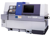
Features of SV-38R
High Functionality
- The 10-position turret type tool post can accommodate a 2-axis power tool unit for B-axis control at a maximum of five positions (Type B only).
- Either a guide bush type or non-guide bush type can be selected according to the total length of parts to machine.
- The 8-axis unit with a Y-axis control function can accommodate a maximum of 6 power tool units.
High Productivity
- The Star Motion Control System shortens the non-cutting time.
- The 8-axis back working unit with a Y-axis control function realizes efficient machining on the main and back sides at the same time.
- The main/sub spindle motors and gang-type tool post power tool motors have improved output power (compared to Star SV-32).
High Rigidity and High Accuracy
- The non-guide bush type incorporates a spindle sleeve slide guideway structure (NOTE 4) for high spindle rigidity.
- Both the main and sub spindles each use a built-in motor, and a built-in sensor improves indexing accuracy.
Major Specifications
| Max. machining diameter | ø38mm | ||
|---|---|---|---|
| Max. head stock stroke | Guide bush type | 350mm | |
| Non-guide bush type | 95mm | ||
| Max. main spindle speed | 7000 min-1 | ||
| Main spindle motor | 7.5kw (cont.)/11kw (10min./25% ED) | ||
| Max. sub spindle speed | 7000 min-1 | ||
| Sub spindle motor | 5.5kw (cont.)/7.5kw (10min./40% ED) | ||
| Gang-type tool post | Ordinary tool | 5 tools | |
| Power tool | 4 tools | ||
| Max. power tool rotation speed | 5000 min-1 | ||
| Power tool motor | 1.2kw (cont.)/2.2kw (5min./30%ED) | ||
| Turret-type tool post | Tool mounting position | 10 positions | |
| Positions with B-axis control | 5 positions (* For Type B only) | ||
| Ordinary tool | Max. 2 tools/position (□16mm) | ||
| Sleeve | Max. 3 tools/position | ||
| Power tool | Max. 2 tools/position | ||
| Max. power tool rotation speed | 5700 min-1 | ||
| Power tool motor | 2.7kw (cont.)/4.0kw (5min/30%ED) | ||
| 8-axis back working unit | No. of tools | [Stationary tool] | 8 tools |
| [Power tool] | Max. 6 tools | ||
| Max. power tool rotation speed | 5000 min-1 | ||
| Power tool motor | 1.2kw (cont.)/2.2kw (5min./30%ED) | ||
| Front-side machining capability | [Stationary tool] | Max. drilling capability | ø23mm |
| Max. tapping capability | M16 × P2.0 | ||
| [Power tool] | Max. drilling capability | ø10mm | |
| Max. tapping capability | M8 × P1.25 | ||
| Rear-side machining capability | [Stationary tool] | Max. drilling capability | ø16mm |
| Max. tapping capability | M12 × P1.75 | ||
| [Power tool] | Max. drilling capability | ø10mm | |
| Max. tapping capability | M8 × P1.25 | ||
| Machine dimensions (W x D x H) | 3420 × 1440 × 1865mm | ||
NOTE 1: Swiss-type automatic lathe
The Swiss-type automatic lathe was devised as watch component processing machinery in Switzerland in 1870s. Known as a “sliding head-type automatic lathe” as well, it has remarkable characteristics of high-precision cutting of components with longer length compared with the diameter.
In general, if long and narrow parts are processed with a general-purpose lathe, flexure will occur on the workpiece, making finishing with the correct dimensions impossible. The Swiss-type automatic lathe utilizes a guide bush to function as a material steady rest. The tool, positioned at a certain distance from the guide bush, gives a cutting motion only the direction of outside diameter. This allows the workpiece to be cut accurately with no flexure. As for axial motion, the headstock, rather than the tailstock, moves while clamping a workpiece.
NOTE 2: Non-guide bush type
This is a sliding head-type automatic lathe which is designed based on the Swiss-type automatic lathe with a guide bush dismounted. Without a guide bush, it is not well suited for machining narrow and long parts. If the workpiece is short and does not deflect, however, such material can be handled effectively.
With the Swiss-type automatic lathe, the rear side of a bar material needs to be handled as waste as a portion equivalent to the size of the guide bush structure which functions as a steady rest for the material cannot be machined. The non-guide bush type reduces the waste to about 1/3 in length compared to the waste made by the guide bush type.
NOTE 3: Star Motion Control System
General machining, when NC-controlled, is composed of the following processes:
[Tool selection] → [Approach] → [Cutting] → [Disengagement] → [Next tool selection] → [Approach] → [Next cutting]
In this process, functions other than actual cutting largely affect the machining time.
The Star Motion Control System is a function to reduce this non-cutting time.
The Star Motion Control data can be created easily by NC program conversion through “optimization”.
This “optimization” finishes processing related the switching of control systems and completes the processes of [Tool selection] and [Approach] during the process of [Cutting], and the [Disengagement] process of the tool and the next [Cutting] process are controlled to start at the same time. By this control method, the time required for the processes of [Disengagement], [Next tool selection] and [Approach] can be minimized to reduce the non-cutting time.
Furthermore, the Star Motion Control System exerts an effect on machining accuracy as well. The NC control system moves each axis at a maximum rapid feed rate to the [Next cutting] process, while the Star Motion Control System moves each axis while taking the shortest way, utilizing the previous [Cutting] process time. This Control System minimizes excessive vibration caused by axis movement at a rapid feed rate and contributes to the maintenance of stable machining accuracy.
NOTE 4: Spindle sleeve slide guideway structure
This structure has a sliding surface machined according to the outer diameter of the head stock spindle sleeve, which moves while clamping the workpiece. By eliminating the gap between the spindle sleeve and the guideway, the structure supports the cutting load applied to the head stock through the slide guideway and improves the head stock rigidity.