Release of Swiss Type Automatic Lathe SR-20RIV
Improvements to our the Best Selling Complex Machine SR Series
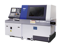
In November, 2012, we will begin to sell a new model SR-20RIV of the Swiss type automatic lathe (NOTE 1) SR series equipped with enhanced functions. This model has been developed to target machining of components in medical- and automobile-related areas.
Since the start of sales of the initial model in 1992, the SR series has been frequently updated to meet the needs of the market. As our best selling complex machines, the total sales of this series have reached 12,000 units.
SR-20RIV accommodates a maximum machining diameter of 20mm. There are two types in this series – Type A with six linear control axes and two rotary control axes, and Type B with a tool swing control axis (B) in addition to the functions of Type A.
Both Types A and B are equipped with a function to select either a guide bush type or non-guide bush type according to the total length of parts to machine. (NOTE 2)
In addition to the portal-type tool post of the uniform load cross guide structure (NOTE 3) for front-side machining with the guide bush arranged in the center, the eight-axis unit with a Y-axis control function is mounted for rear-side machining.
The 27-positioned tool station can accommodate a maximum of 41 tools to allow a variety of tooling layouts.
As for the control, the latest CNC unit is mounted to reduce the time required for program processing. Type B, a higher-end model, is equipped with a unique Star Motion Control System (NOTE 4) to minimize non-cutting time for switching the control system and changing tools.
Features of SR-20RI
High Functionality
- The 27-positioned tool station can accommodate a maximum of 41 tools to allow a variety of tooling layouts.
- The eight-axis unit with a Y-axis control function allows various kinds of complex machining on the rear side.
- The sub spindle employs a spindle motor with an output power equivalent to that of the main spindle to enhance the machining capability on the rear side.
- The power-driven tool motor has an increased power output (compared to that of our
SR-20RIII).
High Productivity
- The eight-axis unit with a Y-axis control function can efficiently divide the process for front-side machining and rear-side machining.
- The latest CNC unit reduces the time required for program processing.
- The Star Motion Control System shortens the non-cutting time. (Type B)
High Rigidity and High Accurac
- The tool post for front-side machining incorporates a “uniform load cross guide structure“ which minimizes a moment load applied to the tool post guide rail during cutting and ensures high rigidity.
- Both the main and sub spindles use a built-in motor. A built-in sensor improves indexing accuracy.
Major Specifications
| Max. machining diameter | ø20mm | ||
|---|---|---|---|
| Max. headstock stroke | 205mm | ||
| Max. main spindle speed | 10000min-1 | ||
| Main spindle rotation control | AC spindle drive (built-in motor) | ||
| Main spindle motor | 2.2kw (continuous)/3.7kw (10min/25% ED) | ||
| Max. sub spindle speed | 10000min-1 | ||
| Sub spindle rotation control | AC spindle drive (built-in motor) | ||
| Sub spindle motor | 2.2kw (continuous)/3.7kw (10min/25% ED) | ||
| Max. power-driven tool speed | 8000min-1 | ||
| Power-driven tool motor | 2.2kw | ||
| Tool post specifications | [For main machining] | Turning tool (12mm2) | 7 pcs. |
| Stationary tool for front-side machining | 4 pcs. | ||
| Stationary tool for deep-hole drilling | 2 pcs. | ||
| Power-driven tool | 6 pos. | ||
| [For back machining] | 8 Pos. | ||
| Front-side machining capability | [Stationary tool] | Max. drilling capability Max. tapping capability |
ø12mm M10 x P1.5 |
| [Power-driven tool] | Max. drilling capability Max. tapping capability |
ø10mm M8 x P1.25 |
|
| Rear-side machining capability | [Stationary tool] | Max. drilling capability Max. tapping capability |
ø12mm M10 x P1.5 |
| [Power-driven tool] | Max. drilling capability Max. tapping capability |
ø 6mm M5 x P0.8 |
|
| Machine dimensions (W x D x H) | 2334 x 1200 x 1695mm | ||
| Machine weight | About 2600kg | ||
NOTE 1: Swiss-type automatic lathe
The Swiss-type automatic lathe originated as watch component processing machinery in Switzerland in the 1870s. Known as a “sliding head-type automatic lathe“ as well, it has the remarkable characteristics of high-precision cutting of components with longer length compared with the diameter.
In general, if long and narrow parts are processed with a general-purpose lathe, flexure will occur on the workpiece, making the finishing with the correct dimensions impossible. The Swiss-type automatic lathe utilizes a guide bush to function as a steady rest for the material. The tool, positioned at a certain distance from the guide bush, exert cutting motion only to the direction of outside diameter. This allows the workpiece to be cut accurately with no flexure. As for axial motion, the headstock, rather than the tailstock, moves while clamping a workpiece.
NOTE 2: Non-guide bush type
This is a sliding head-type automatic lathe which is designed based on the Swiss-type automatic lathe with a guide bush dismounted. Without a guide bush, it is not well suited for machining narrow and long parts. If the workpiece is short and does not deflect, however, such material can be handled effectively.
With the Swiss-type automatic lathe, the rear side of a bar material needs to be handled as waste as a portion equivalent to the size of the guide bush structure which functions as a steady rest for the material cannot be machined. The non-guide bush type reduces the waste to about 1/3 in length compared to the waste made by the guide bush type.
NOTE 3: Uniform load cross guide structure
The gang-type tool post of the CNC automatic lathe is composed of X-axis and Y-axis slide tables. Each axis is usually supported by four linear guide bearings (eight linear guide bearings in total).
The uniform load cross guide structure indicates a structure of the tool post equipped with eight linear guide bearings evenly arranged around the guide bush as a cutting point to generate a load.
By distributing the cutting load to eight linear guide bearings, the load applied to each linear guide bearing is minimized and the tool post rigidity is improved.
The employment of this tool post structure enables extended continuous operation with stable accuracy and prolongs the service life of the linear guide bearings.
NOTE 4: Star Motion Control System
General machining, when NC-controlled, is composed of the following processes:
[Tool selection] → [Approach] → [Cutting] → [Disengagement] → [Next tool selection] → [Approach] → [Next cutting]
In this process, functions other than actual cutting largely affect the machining time. The Star Motion Control System is a function to reduce this non-cutting time.
The Star Motion Control data can be created easily by NC program conversion through “optimization“.
This “optimization“ finishes processing related the switching of control systems and completes the processes of [Tool selection] and [Approach] during the process of [Cutting], and the [Disengagement] process of the tool and the next [Cutting] process are controlled to start at the same time. By this control method, the time required for the processes of [Disengagement], [Next tool selection] and [Approach] can be minimized to reduce the non-cutting time.
Furthermore, the Star Motion Control System exerts an effect on machining accuracy as well. The NC control system moves each axis at a maximum rapid feed rate to the [Next cutting] process, while the Star Motion Control System moves each axis while taking the shortest way, utilizing the previous [Cutting] process time. This Control System minimizes excessive vibration caused by axis movement at a rapid feed rate and contributes to the maintenance of stable machining accuracy.